APPLICATION · RUBBER AND COMPOSITE
EDGE AND SYMMETRY REFERENCE
IN REINFORCEMENT LAYUP
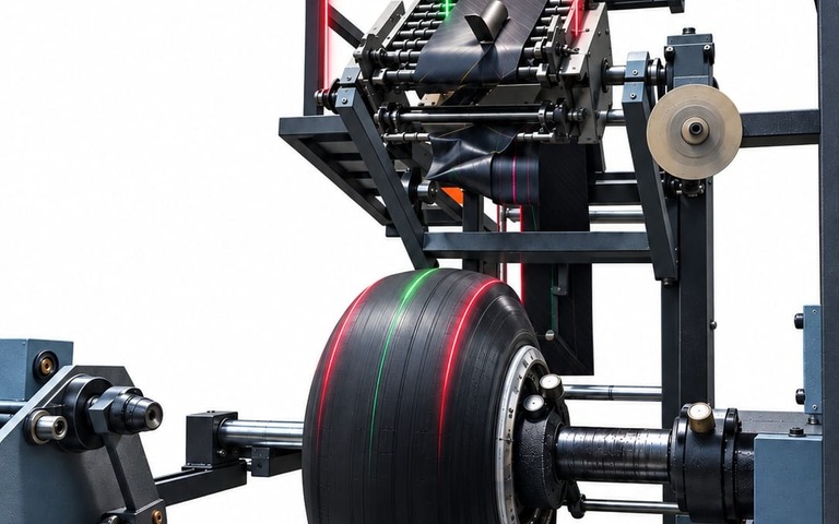
Reinforcement ply layup width changes from product to product. Every changeover means re-establishing the edge position and the symmetry axis, and setting them by eye makes the result depend on the operator and on the time available. ServoMotion reads the target positions from the recipe and projects the laser reference lines onto the working surface.
FROM THE FIELD
Application Images
ON THE LINE
DO THESE
SOUND FAMILIAR?
When the layup width changes, the edge and symmetry reference is rebuilt from scratch, making setup the longest item in the changeover.
On a cylindrical or curved surface, centring the ply depends on the operator’s viewing angle. The same product is set up differently across shifts, resulting in inconsistent output.
Ply misalignment goes unnoticed during layup, and by the time it appears at the next stage, correcting it is expensive.
Fixed guides and templates shift with vibration and contact, and need periodic readjustment.
WHAT WE MEASURE ON SITE
PARAMETERS THAT
DEFINE THE SYSTEM
The parameters below drive the design decisions in this segment. We measure these values on your line and base the quotation on that data.
| Layup width range | The difference between the narrowest and widest product determines the housing length and the travel range. |
|---|---|
| Symmetry axis | Whether the centre reference must remain visible continuously determines the channel configuration. |
| Surface geometry | Flat, curved or cylindrical geometry affects the projection angle and the mounting height. |
| Working distance | The vertical distance between the laser and the surface determines line width and angular tolerance. |
| Support structure | An existing frame or a new traverse; rigidity translates directly into accuracy. |
| Vibration and environment | Line vibration, surface colour and overhead lighting all influence the choice of laser colour. |
SYSTEM SELECTION
WHICH ARCHITECTURE
FOR THIS SEGMENT?
MOST APPLICATIONS
CORE PRECISOR
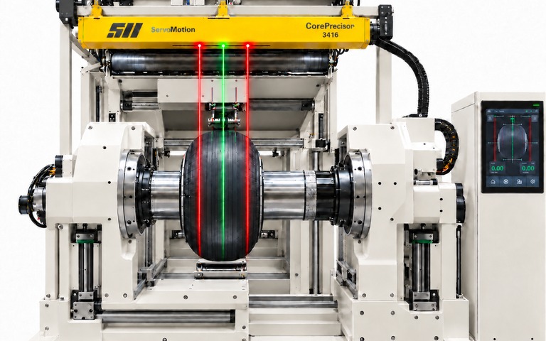
In reinforcement layup, the number of simultaneous reference lines is usually limited. An enclosed industrial profile drives to the target positions under servo control, and where symmetry is required, a dual-channel configuration keeps the centre reference continuously visible.
Explore Core Precisor →IF THE NUMBER OF PROJECTED LASER LINES GROWS
SHUTTLE PRECISOR
If more than six lines must be visible at once, the shuttle architecture — a single servo axis positioning multiple laser carriages — takes over. The decision is based on the densest recipe in your portfolio.
Explore Shuttle Precisor →EXAMPLE INSTALLATION
CORE PRECISOR · K4 DUAL CHANNEL · 1,600 MM TRAVEL
Two independent motion channels plus a fixed centre reference on a separate bracket. In symmetrical layup, both edges are positioned simultaneously while the centre line stays visible throughout production. These figures come from one example installation; the dimensions for your line are determined during the site survey.
RELATED ARTICLES
WHAT WE HAVE
WRITTEN ON THIS
APPLICATION NOTE
REQUEST THE
APPLICATION NOTE
The application note is shared as a PDF on request.
LET'S ASSESS YOUR LINE TOGETHER
Share your layup width range and mounting structure, and we will define the system configuration and housing dimensions together.