Layer and edge alignment
Shows the target edge positions as laser lines while material and parts are placed. The operator works to those references. The projection layout is set from the working surface and the geometry of the application.
SERVOMOTION · SEQUENTIAL LASER POSITIONING
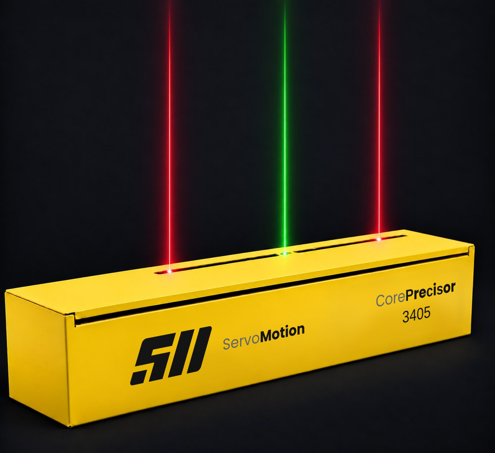
Core Precisor moves laser lines automatically to target positions set by servo control. Independent or symmetrical motion options match the system to different alignment needs, and recipe-based control provides a repeatable position reference across shifts.
Application areas
Core Precisor projects the positions held in the recipe onto the working surface as laser lines. By making material edges, the centre axis and setup points visible, it gives the operator an alignment reference across different production processes.
Shows the target edge positions as laser lines while material and parts are placed. The operator works to those references. The projection layout is set from the working surface and the geometry of the application.
When the product size changes, the lasers move to the new target positions. While guides, stops or cutting elements are set, the figure from the recipe is shown directly in the working area.
A fixed laser marks the centre axis while the moving lasers mark the target positions on either side. This gives centring, width setting and symmetrical placement one shared reference.
Contribution to production
Showing the recipe dimensions directly in the working area lets material placement and machine setup run from the same references.
Laser lines make the target positions visible on the surface. This helps reduce manual measurement transfer and keeps the reference in view during placement.
The positions belonging to a new recipe are shown by servo-controlled motion. How much setup time this saves depends on the layout of the application and on what the operator does.
References defined for a product can be reused, so different operators place and align to the same targets.
Working principle
PLC-controlled servo axes carry the laser modules to the defined targets. The projected laser reference lines guide material placement or machine setting, while the operator carries out the physical alignment. The position is not a one-off setting made at installation — it is recipe data.
Position and width values for the product are entered at the control interface.
The PLC sends the position commands to the servo axes for the selected movement configuration.
The lines travel to their target positions under closed-loop control and stop there.
The references stay in place, and the same recipe returns the lines to the same positions on each run.
The laser modules, servo axes and cabling sit inside a closed housing. Dust, fibre and moisture from the line cannot reach the moving parts; cleaning is limited to the outer surface and the laser window.
The fixed laser in the centre never moves. Symmetrical recipes are set up around this line, so the machine centre can be verified at any time without measuring.
In dual-channel and symmetrical configurations two lasers move at the same time; the same number of steps shows twice as many line positions.
The system is mounted over the line as a single housing. No rail along the machine, carriage park zone or extra chassis is required.
On lines with few reference lines, one or two axes are enough. Cost follows the number of lines actually needed, not the width of the machine.
Motion configurations
Core Precisor provides independent and symmetrical laser motion in a single- or dual-channel axis layout, with a fixed centre reference laser added where it is needed. Select a motion configuration and see how the laser modules position themselves across a 1,200 mm working width. The view is schematic; travel limits and module layout follow the requirements of the application.
The view is schematic. The time assumes 1,000 mm/s and a 0.25 s dwell per step; the actual acceleration profile, the spacing between modules and the operator’s own setting time are not modelled, so it is not the total setup time.
Features
Travel, projection conditions and control infrastructure are assessed together, so the laser reference suits the line’s setting method and working area.
The positional accuracy of the target line. Working distance and mounting conditions are assessed during selection.
High-dynamic motion that shortens positioning time between recipe positions.
Red or green laser options on both fixed and moving modules. Colour is chosen to suit the working surface and the ambient lighting.
Options for communicating with the line control system. Protocol and connection scope are defined during the project.
Housings from 600 to 4,000 mm, with longer housings designed on request. Usable travel and mounting layout follow the dimensions of the application.
A cover that opens and closes easily for laser replacement and calibration.
Mechanical design for your machine
Core Precisor housings are sized to the working width and mounting conditions of your line. Housing length, usable travel and mounting points are set from your machine drawings. The diagram below shows how usable travel relates to housing length — the two are not the same figure.
The drawing assumes an example layout with 80 mm clearance at each end. Usable travel is confirmed per project from the laser module size, the end limits and the chosen configuration.
System components
The laser modules, the PLC and the servo axes work together to project the target positions onto the working surface. The operator panel gives access to recipes and setup parameters.
Specifications
| Laser colour | Red or green |
|---|---|
| Line width | 1 mm |
| Focus | Adjustable |
| Laser supply | 12–24 VDC |
| Laser protection class | IP54 |
| Laser class | Classified to IEC 60825-1 · Class 2M or 3R depending on the selected optical power; the exact class is stated on the product label and in the user manual |
| Wavelength | Red 635–660 nm · green 515–532 nm · depending on module |
| Laser connector | M12, 4 pin |
| Projection accuracy | ± 1.00 mm |
|---|---|
| Positioning speed | up to 1000 mm/s |
| Housing / rail assembly length | up to 4,000 mm · longer on request |
| Movement configurations | 6 models (K1–K6) |
| Travel distance | Customised to the machine |
| Service access | Damped hinged cover |
| Rail assembly protection class | IP54 · higher protection on request |
| System weight | Varies with application and housing length · stated in the quotation |
| Mounting interface | Defined per application · adapter plate to the existing frame or a new support |
| Controller | Industrial PLC |
|---|---|
| Drive | Servo drive |
| Protocol | Industrial fieldbus (PROFINET · EtherNet/IP™) |
| Axis management | Independent and symmetrical motion control |
| Position feedback | Closed-loop control with encoder |
| Diagnostics | Status and fault monitoring |
| Supply | 220 V AC 50 Hz · from the control cabinet |
| Power consumption | Varies with laser count and configuration · given in the project file |
| Operating environment | Enclosed production area · +10 … +40 °C · 10–90 % RH, non-condensing |
| Display | PCAP touch screen |
|---|---|
| Processing / storage | Industrial platform · solid-state storage |
| Interfaces | Industrial and peripheral connection options |
| Network | Ethernet and wireless options |
| Video output | External display connection |
| Supply | DC supply |
Values apply to example configurations. Final performance and connectivity are evaluated together with motion load, working distance and mounting conditions.
SAFETY
The class of the line laser module used in the system is stated on the product label and in the user manual delivered with it. Modules must be operated under the conditions defined in that manual.
The beam must not be viewed directly. Reflection angles on glossy surfaces are assessed together during installation, and the operator’s working position is reviewed at commissioning.
The system must be de-energised and the line brought to a safe state before optics cleaning and mechanical checks.
The industrial positioning laser modules used in the system have been assessed against EN 55011 and EN 55032 electromagnetic compatibility requirements and certified by TÜV Rheinland LGA Products GmbH (Cert. No. AK 50498967 0001). Request the certificate.
The declaration of conformity and the technical file for the delivered system are supplied with the delivery package, project by project.
Same Brand · Different Architecture
If the number of cutting lines exceeds six and the lines must stay on together throughout production, Shuttle Precisor — one servo shuttle positioning dozens of laser carriages — is designed for the job.
Send us the alignment requirements of your line; we will design an optimised laser layout, precise motion control and PLC/automation integration specifically for your system.
We share technical articles, application examples and product updates by email as they are published, to make system selection and investment decisions easier.
Sign up for the e-newsletter
Your email address is processed only to send the newsletter, and you can unsubscribe at any time. For details, see our privacy notice.