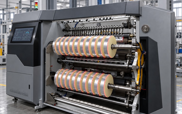
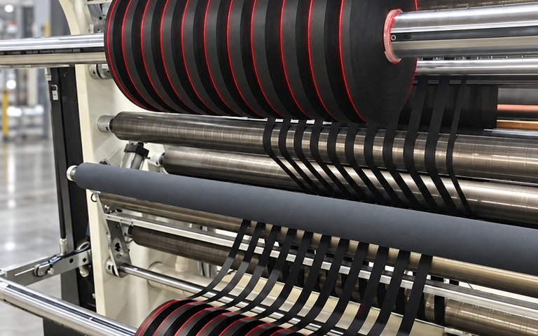
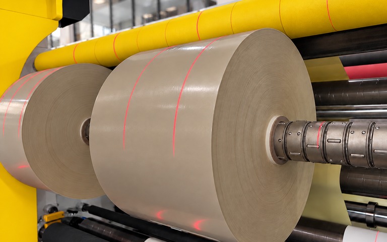
Both systems project the alignment reference under PLC and servo control. What separates them is how many lines have to stay visible at the same time.
UP TO SIX LINES · SEQUENTIAL
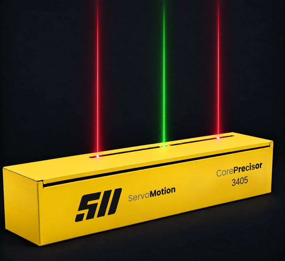
CORE PRECISOR
A servo-driven laser alignment system in an enclosed housing. Laser lines move to the positions held in the recipe, and six movement configurations cover independent and symmetrical alignment needs.
A three-rail shuttle architecture. A single servo axis carries each laser carriage to its recipe position in turn; every carriage then locks mechanically, so all lines stay visible throughout production.
The defined edge and axis positions are projected onto the working surface as laser lines. The operator places the material or part against a shared reference, which reduces the need to transfer measurements by hand.
02 / MACHINE SETUP
A CONTROLLED SETUP PROCESS
The target positions of guides, stops and processing elements are shown by the laser references. Being able to follow the setup points directly in the working area simplifies commissioning and cuts repeated measurement steps.
03 / PRODUCT CHANGEOVER
REPEATABILITY FROM THE RECIPE
Position data for each product is held in the recipe and reapplied under PLC control at the next changeover. Returning to the same reference layout supports a standard setup method and shortens preparation between products.
CATEGORY DIFFERENCE
NOT A FIXED SETTING.
POSITIONING BY RECIPE.
Traditional fixed reference
The laser is set once at commissioning. Every recipe change then means re-adjusting the line by hand, so the result depends on who does it, how it is measured and how much time is available.
Servo-controlled reference
Dimensions are entered at the panel and the system drives to the target positions itself. Call up the same recipe and the lines return to the same place — changeover becomes a machine task rather than an operator task, improving changeover repeatability.
±1.00mmProjection accuracy
1000mm/sPositioning speed · Core
5–40+carriagesLaser carriages · Shuttle
TECHNICAL COMPARISON
SAME REFERENCE.
DIFFERENT MOTION ARCHITECTURE.
Criterion
Core Precisor
Shuttle Precisor
Architecture
Servo-driven laser alignment system in an enclosed housing6 movement configurations
Multi-laser alignment system on a three-rail shuttle structureSingle servo drive, multiple locked carriages
Lines visible at once
As many as the number of lasers in the housingRemaining lines are shown in turn by recipe steps
All cutting linesSimultaneous and continuous once the recipe is set
Typical number of lasers
1 – 6
5 – 40+
Number of servo axes
1 axis per moving laser
1 shuttle axis in total (single drive)
Suitable applications
Slitting with few slits, blade alignment, single-reference lines
Multi-slit slitting, calender and wide-web lines, elastic/ear feeding
After setup
Lasers move to the next recipe position
The shuttle returns to its home position, all lines stay in place
Housing length
600 – 4,000 mmLonger lines are designed on request
Travel + reserve area + safety marginScaled to the project · the configurator calculates
Common infrastructure
Industrial PLC and servo drive control
Integration into line automation via a standard fieldbus
Touchscreen operator panel
Industrial line laser modules
Final performance and connectivity are assessed together with motion load, working distance and mounting conditions. The lasers provide an alignment reference; adjustment of material and machine elements remains with the operator.
INDUSTRIAL APPLICATIONS
DIFFERENT PROCESSES
ONE ALIGNMENT APPROACH
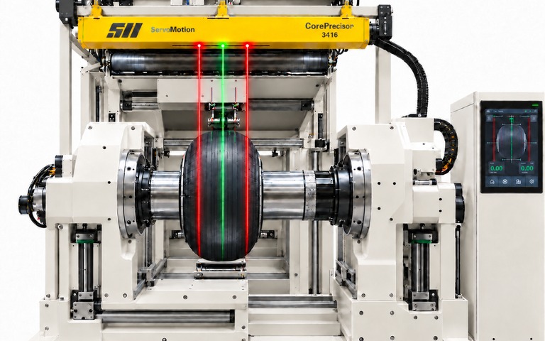
RUBBER AND COMPOSITE
The lay-up width of the reinforcement plies changes from product to product, so the edge and symmetry reference has to be re-established at every changeover. The reference lines follow the geometry of the application surface.
Decisive factorsPly width, symmetry axis, geometry of the application surface and working distance.
EXAMPLE INSTALLATION Core Precisor · K4 dual channel (1 fixed + 2 moving) · 1,600 mm travel
Every layer in a multi-ply structure needs a consistent edge and axis reference, while the product size changes often. When the size changes, the alignment positions are rebuilt from the recipe.
Decisive factorsNumber of layers, working width, number of simultaneous reference lines and the optical behaviour of the nonwoven surface.
EXAMPLE INSTALLATION Shuttle Precisor · 26 lasers · 2,300 mm travel
Changing between formats holds the line while guides and processing elements are reset. A shared position reference keeps the same setup discipline across formats.
Decisive factorsFormat variety, recipe change frequency and the number of reference lines that must be visible at the same time.
EXAMPLE INSTALLATION Shuttle Precisor · 16 lasers · 1,800 mm travel
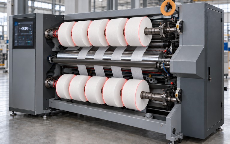
The job usually starts with where the two edges sit. Reel width and slit width change from recipe to recipe, so the edge position has to be re-established at every changeover.
Decisive factorsSurface optics, distance between the edges, laser colour and working distance.
EXAMPLE INSTALLATION Core Precisor · K3 single channel + fixed (1 moving + 2 fixed references) · 2,000 mm travel
Symmetry matters as much as edge position. Once the centre axis is lost the product comes out off-centre even when the edges are correct, so the centre reference has to stay visible throughout production.
Decisive factorsLay-up width, centre axis, ply arrangement and mounting height.
EXAMPLE INSTALLATION Core Precisor · K4 dual channel (2 moving + 1 fixed centre) · 2,400 mm travel
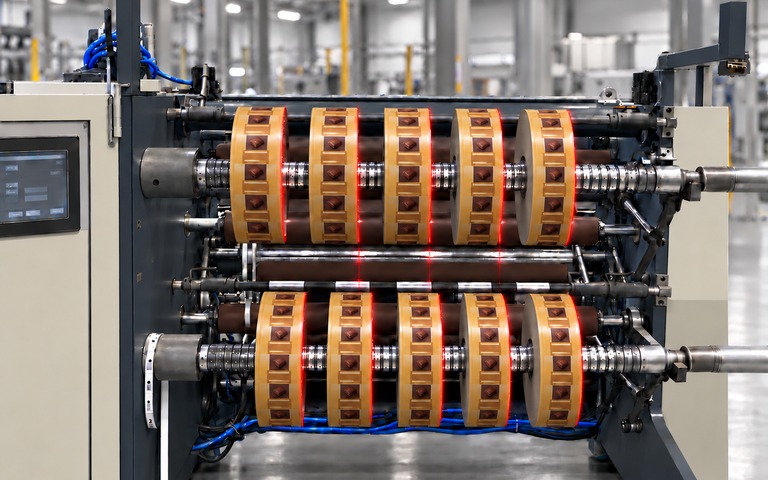
In narrow-width slitting a single recipe means dozens of cut positions. Measuring and setting them one by one can become the longest stoppage on the line.
Decisive factorsLine spacing, number of simultaneous reference lines and mechanical layout.
EXAMPLE INSTALLATION Shuttle Precisor · 20 lasers · 1,800 mm travel
OEM Lazer has been developing industrial laser applications since 2014. In ServoMotion systems we bring mechanical design, laser placement and servo motion control together with PLC automation. The working area, the mounting conditions and the process requirements are assessed together, and the system structure is set from that. Our engineering work runs through to installation, commissioning and integration into the production line.
We share technical articles, application examples and product updates by email as they are published, to make system selection and investment decisions easier.
Sign up for the e-newsletter
Your email address is processed only to send the newsletter, and you can unsubscribe at any time. For details, see our privacy notice.